| [HERACLES DESIGNER GUI VERSION-1.0 USER’S GUIDE] |
Screen Shots
Heracles Designer is the Graphical User Interface for quick system configurations. In the configuration
folder, there are two setting examples.

On top of the home tag are the different tabs to configure the system.
On the core setting tab, user can specify:
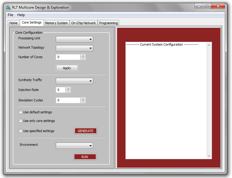
1- The type of core to generate, in the version v1.0 of the Heracles GUI only MIPS and Injector cores are
fully supported.
2- The network topology of the system instance to generate. Note that only 2D-Mesh is supported in
version v1.0 of GUI.
3- The number of cores to generate. After the number of cores is specified, the “Apply”
button is used to
update the “On-Chip Network” and “Programming”
tabs to reflect the core count.
4- The traffic type, injection rate, and simulation cycles, used to generate traffic for the injector core.
5- Different settings, “Use of default settings” is to enable fast testing of a system, by generating key
parameters.
Note: “Generate” and “Run” buttons are very important.
The “Generate” button generates the Verilog file for
the system instance. The “Run” button generates the appropriate .tcl file to launch the system in the
environment specified, in version v1.0, ModelSim environment is the one tested.
Memory system tab allows user to set:
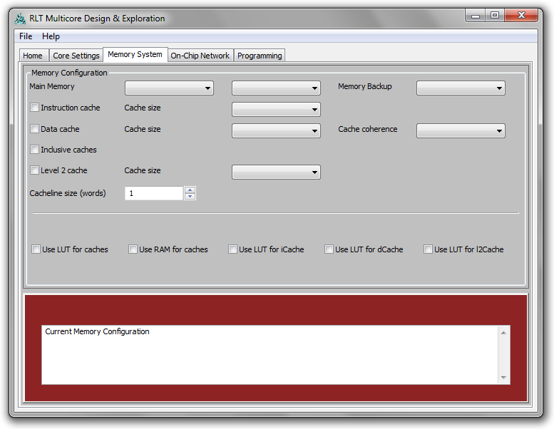
1- Maim memory configuration, “Uniformed Distributed”
for the main memory is the default.
The total size is shared among the number of cores instantiated.
2- Instruction and data caches.
Note: In version v1.0 of the GUI, main memory backup, cache coherence, and level 2 cache setting
are not supported.
The on-chip network tab covers all the major aspects of the system interconnect that the user can set:

1- Routing algorithm.
2- Number of virtual channels (VCs) per port and depth of each 3- Core and switch bandwidths, but only
advanced users who understand the implications should change bandwidths from 1.
4- Routing tables, by selecting source/destination pair or flow ID, router ID, output port, and VC (this
allows for more flexible user defined routing paths).
5- Source and destination pairs manually, in the manual routing section, for injector-based traffic, where
user is setting source and destination pairs manually. It should not be used for the MIPS- based cores,
because source and destination traffic is dictated by application and memory mapping.
6- Number of flits per packet for injector-based traffic.
The programming tab is updated when user changes the number of cores in the system, user can:
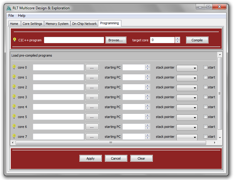
1- Load a binary file onto a core.
2- Load a binary onto a core and set the starting address for another core to point to that binary.
3- Select where to place the data section or stack pointer of a core (it can be local, on the same core as
the binary or on another core).
4- Select which core to start.
5- Any error loading the binaries with show up on the core setting tab.
Note: When using the injector this tab is not active. Also in the version v1.0 of the GUI, the automatic compiling
of a C or C++ is not supported. On that version, user must manually move the softwareToolchain folder to
his/hers own linux-based environment to compile the programs then move the binaries back.